Locking "B" Mandrel
Tools International Corp
Description
Specifications
Assembly
Components
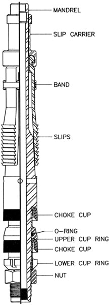
Description
The Type “B” Mandrel is designed to be used in well completions that have not been equipped with landing nipples. It can be lowered to any desired depth and attached to the tubing wall as a means to set safety valves, regulators and flow beans. The Type “B” Mandrel can only hold pressure from below.
| SPECIFICATIONS | ||||
|---|---|---|---|---|
1 1/2" |
1 3/4" |
2" |
2 1/2" |
|
FISHNECK O.D. |
1.188" |
1.188" |
1.375" |
1.750" |
MAX. O.D. (Slips Expanded) |
1.703" |
1.820" |
2.078" |
2.540" |
MAX. O.D. (Slips Retracted) |
1.480" |
1.590" |
1.859" |
2.300" |
MINIMUM I.D. |
9/16" |
9/16" |
11/16" |
7/8" |
BOTTOM THREAD |
7/8"-14 |
7/8"-14 |
1 3/16"-14 |
1 9/16"-12 |
RUNNING TOOL |
41W01150 |
41W01150 |
41W01200 |
41W01200 |
PULLING TOOLS |
40RB1150 |
40RB1150 |
40RB1200 |
40RB1250 |
OR 40JUC150 |
OR 40JUC150 |
OR 40JUC200 |
OR 40JUC250 |
| COMPONENTS | ||||
|---|---|---|---|---|
1 1/2" |
1 3/4" |
2" |
2 1/2" |
|
Mandrel |
10B00196 |
10B00196 |
10B00204 |
10B00204 |
Slip Carrier |
10B00991 |
10B00332 |
10B01331 |
10B01336 |
Band |
10A01608 |
10A01608 |
10A01609 |
10A01610 |
Slip |
(3) 10B00992 |
(3) 10B00988 |
(3) 10B01639 |
(3) 10B00876 |
Upper Cup Ring |
10B00195 |
10B00195 |
10B00202 |
10B00224 |
Choke Cup |
(2) 81CC0150 |
(2) 81CC0163 |
(2) 81CC0179 |
(2) 81CC0313 |
Lower Cup Ring |
10B00197 |
10B00197 |
10B00203 |
10B00222 |
Nut |
10B00198 |
10B00198 |
10B00201 |
10B00220 |
O-Ring |
#212 |
#212 |
#217 |
#222 |